
Course Content
Formula Sheet
Example 1
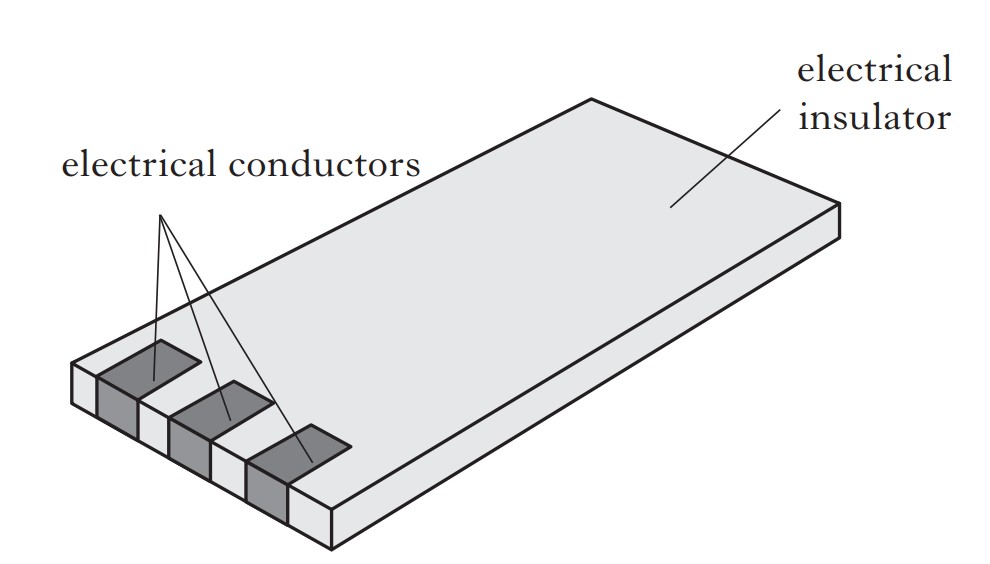
The picture shows a typical mobile phone battery.
The battery is completely discharged. A current of 800 mA is then supplied for 2 hours.
This charges the battery fully.
(i) Define the term current.
(ii) Calculate the total charge supplied to the battery.
(iii) When in use, the fully charged battery supplies a constant current of 50 mA.
Calculate the time taken for the battery to completely discharge.
(i) The current is defined as the rate of flow of charge.
(ii) We use the formula and remember to convert to seconds:
Q = It
Q = 800 x 10-3 x 60 x 60 x 2
Q = 5760 C
(iii) We use the same formula and re-arrange for time:
Q = It
t = Q⁄I
t = 5760⁄50 x 10-3
t = 115200s
Note: If you're ever unsure on what to do in a question, list all your data e.g Q = 5760 C and look at the formulas that relate them.
Example 2
A student sets up the following circuit using a battery, two lamps, a switch and a resistor.
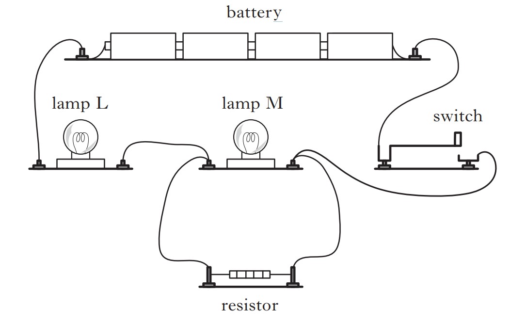
(a) Each lamp is rated at 2.5 V, 0.50 A.
Calculate the resistance of one of the lamps when it is operating at the correct voltage.
(b) When the switch is closed, will lamp L be brighter, dimmer or the same brightness as lamp M?
You must justify your answer.
(a) We use the formula:
V = IR
R = V⁄I
R = 2.5⁄0.5
R = 5 Ω
(b) To get full marks on this question, you must state the result and give a reason why.
Here, lamp M is in parallel with a resistor, and using our knowledge of circuits we know that current splits up across branches in a parallel circuits.
The current will then be the full value as it flows through lamp L in series.
This means more current will flow through lamp L compared to lamp M, meaning lamp L will be brighter. So:
Lamp L will be brighter, as more current will flow through lamp L compared to lamp M, as the current divides between lamp L and the resistor in parallel with it.
Example 3
A security floodlight is used to automatically illuminate an area outside a building when it gets dark.
The circuit for this system is shown.
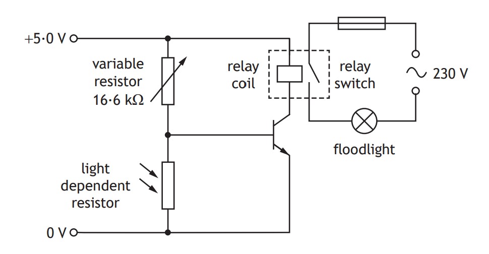
The resistance of the variable resistor is set to 16.6 kΩ.
The _____ in this circuit has a switch on voltage of 0.7 V.
(a)(i) Identify the circuit symbol used to automatically complete the circuit when a voltage of 0.7 V is across it.
(a)(ii) Name another circuit component that could be used to automatically complete the circuit when a certain voltage is across it.
(b)(i) The light level decreases to the point where the resistance of the light dependent resistor is 3.4 kΩ.
Show by calculation that the transistor is switched on at this light level.
(b)(ii) Explain how the circuit operates to switch on the floodlight when the light levels fall below a certain value.
(b)(iii) The resistance of the variable resistor is now increased,
What effect does this have on the light level at which the floodlight is switched on?
You must justify your answer.
(c)(i) The floodlight is connected in a part of the circuit controlled by a relay.
The floodlight has a power rating of 575 W.
Calculate the current in the floodlight when it is switched on.
(c)(ii) The following fuses are available for use with the floodlight.
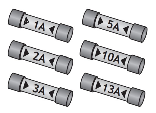
State which one of these fuses is the most appropriate for use with the floodlight.
(a)(i) The circuit symbol is a transistor
(a)(ii) MOSFET
(b)(i) There are many ways to do this question. Personally, I would use:
V1⁄VTOTAL = R1⁄RTOTAL
V1⁄5 = 3.4 x 10³⁄16.6 x x 103 + 3.4 x 10³
V = 5 x 3.4 x 103⁄20 x 103
V = 0.85 V
(b)(ii) This question is commonly observed to appear in the exam.
Make sure you know how to answer this question and how the circuit work.
A helpful way to remember how these circuits work is "LURD"(Light Up Resistance Down) for LDRs and "TURD"(Temperature Up Resistance Down) for thermistors.
As the light level decreases, the resistance of the LDR increases, meaning the voltage across the LDR increases. The voltage increases until it reaches 0.7 V, with which the transistor turns on. The relay activates and completes the floodlight circuit.
(b)(iii) Since the resistance of the variable resistor is increased, there will be a greater voltage across it, and therefore the voltage across the LDR decreases.
This means for the same light level before the change of the variable resistor's resistance, the base voltage across the transistor will be lower.
The LDR will require a lower light level for the resistance to increase enough to increase the voltage for the transistor to switch on and activate the relay. So:
Light level would be lower, as the resistance of the LDR must be greater than 3.4 kΩ for the transistor to switch on and activate the relay.
(c)(i) From the diagram, we can see the floodlight has a voltage of 230V.
In the question, we are given the power rating of the floodlight.
Using the formula that relates all these values:
P = IV
I = P⁄V
I = 575⁄230
I = 2.5 A
(c)(ii) In this question, we would usually use the formula P = IV to calculate the current and select the first fuse that has a bigger value than the current
Since we just calculated current in the previous question, we can go to the answer.
The 3 A fuse is most appropriate. (Since 3 A > 2.5 A)
Note: other questions may not give fuses to choose from. In this case you choose between a 3 A or 13 A fuse.
Example 4
A circuit is set up as shown.
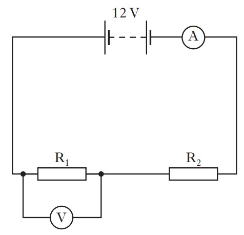
The reading on the ammeter is 3 A
The reading on the voltmeter is 4 V.
Calculate the current in resistor R2 and the voltage across R2
Using our knowledge of series circuits, we know that the current is the same and the voltage splits up between components.
This means the current in R2 is 3 A.
To get the current, we take away the voltage across R1 from the total voltage.
Current in R2 = 3 A
Voltage in R2 = 12 - 4 = 8 V
Example 5
A mains electric fire has two heating elements which can be switched on and off separately.
The heating elements can be switched on to produce three different heat settings: LOW, MEDIUM and HIGH.
The fire also has an interior lamp which can be switched on to give a log-burning effect.
The circuit diagram for the fire is shown.
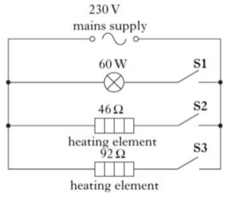
(a) When switch S1 is closed, the lamp operates at its stated rating of 60W.
Calculate the current in the lamp.
(b) Switch S1 is opened and switches S2 and S3 are closed.
(i) Calculate the combined resistance of both heating elements.
(ii) Calculate the total power developed in the heating elements when S2 and S3 are closed.
(iii) State which switch or switches would have to be closed to produce the LOW heat setting.
You must justify your answer.
(a) We use the formula that relates power, current and voltage:
P = IV
I = P⁄V
I = 60⁄230
I = 0.26 A
(b)(i) To calculate the combined resistance, we use the formula for parallel circuits:
1⁄RTOTAL = 1⁄R1 + 1⁄R2
1⁄RTOTAL = 1⁄46 + 1⁄92
1⁄RTOTAL = 3⁄92
RTOTAL = 90⁄3
RTOTAL = 30.7 Ω
(b)(ii) We can calculate the total power in the heating elements in multiple ways.
The easiest way is to realise that we have the total resistance and the voltage (as the heating elements are in parallel with the battery, so it's just 230 V).
So we can use the formula.
P = V2⁄R
P = (230)2⁄30.7
P = 1720 W
(b)(iii) Lets think this through. A low heat setting would mean we would need the heating with the biggest resistance as this would mean it would have less current flowing through it, and therefore produce less heat.
S3 would need to be closed, as the heating element in that branch has the greatest resistance, meaning the lowest value of current will flow through it.
Note: It is correct to talk about how the greatest resistance will produce the lowest power output of the heating element.
Example 6
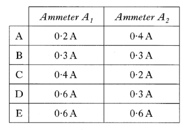
Three identical resistors are connected with three ammeters to a d.c. supply as shown
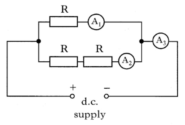
The reading on A3 is 0.6 A.
Which row in the table shows the readings on A1 and A2?
Lets use our knowledge of parallel and series circuits:
We know that in series, the current is the same. This means the 0.6 A will split between the two branches and then come together after the parallel branches.
Since the three resistors are identical, the current will split in a ratio. Since there is only one resistor in the branch of A1, the resistance will be smaller than that in the branch of A2.
This means the current in the top branch will be greater than that in the bottom branch.
Looking at our options in the table, the only row that make sense is C.
So the answer is C
Example 7
An electric field exists around two point charges Q and R.
The diagram shows the path taken by a charged particle as it travels through the field.
The motion of the particle is as shown.
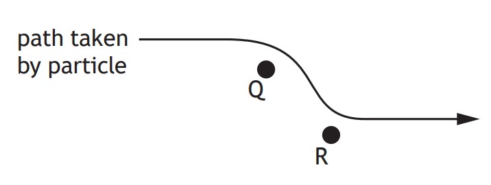
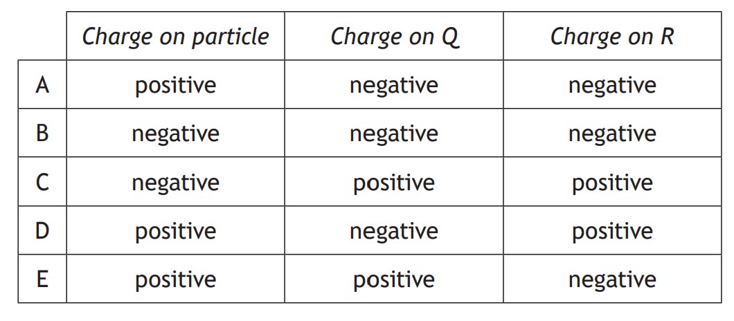
Which row in the table identifies the charge on the particle,
the charge on Q and the charge on R?
In this question, we need to think through logically.
It can help to trace the path of the particle as if Q or R weren't there.
If Q wasn't there, the particle would continue in a straight line to the right.
However when Q is present, it attracts the particle, causing it to move downwards.
This means that Q and the particle are opposite charges, as opposite charges attract eachother.
If R wasn't there, the particle would continue in a straight line downwards.
However when R is present, it repels the particle, causing it to move to the right.
This means that R and the particle are the same charge, as like charges repel eachother.
The only row in the table that makes sense is D.
So the answer is D